

🔊 Amplify your vibe, not your footprint!
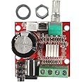
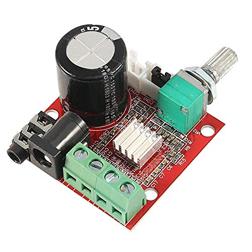
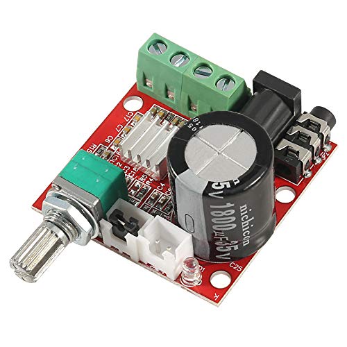
The HiLetgo PAM8610 Mini Stereo Amplifier is a compact, energy-efficient Class-D amp delivering 10W per channel stereo output. Featuring a high 90% efficiency rating, it operates safely with built-in protections against over-current, temperature spikes, and short circuits. Designed for easy use with LED indicators and mute switch, it runs on a recommended 12V DC power supply, making it an ideal upgrade for professional and personal audio setups.
| Item dimensions L x W x H | 15.75 x 15.75 x 15.75 inches |
| Voltage | 15 Volts |
| Manufacturer | HiLetgo |
| Maximum Supply Voltage | 15 Volts (DC) |
| Minimum Supply Voltage | 7.5 Volts (DC) |
| Mounting Type | Surface Mount |
| Brand | HiLetgo |
| Number of Channels | 2 |
| Output Power | 2E+1 Watts |
| Package Type Name | product box |
| Specification Met | 12v Power Supply Voltage Standard |
| Supply Current | 2E+1 Milliamps |
| UPC | 698775174615 |
| Item Weight | 0.634 ounces |
| Product Dimensions | 15.75 x 15.75 x 15.75 inches |
| Item model number | 3-01-0453-A |
| Is Discontinued By Manufacturer | No |
| Color | Red |
| Number of Items | 1 |
| Size | Small |
| Manufacturer Part Number | 3-01-0453-A |
D**
calidad y cumplimiento
excelente productomuchas gracias
G**B
Good product and $, fast shipping. Very good presentation.
Good product and $, fast shipping.
H**T
Punchy little amp with some inconsistency
First off, it’s tiny. Secondly, I’m not sure what happened but the LED died and the output became very noisy and then just loud. I was using it to power some vintage alnico drivers at 8 ohms with very smooth and impressive results but then after physically moving the board it started making the power-off pop when I zeroed the volume.Other than this, I really quite like the little fella and just ordered a second one for another project.
K**N
Waste of money
No documentation, no diagrams to connect any portion of circuit. Once connected, did not work. Recommend pass this by and NOT consider.One example (after it did not work), buried at the end of the listing :Operating voltage: DC 7.5-15VRecommended power supply voltage: 12VPCB board size: (40 * 40) mmPower Interface: 5.5 socketNOTE:1. The power supply voltage can not exceed 12VWHY say the voltage can go to 15v in MULTIPLE PLACES and then a notation virtually hidden not to exceed 12v. Not sure if this is the root cause of the failure, used a wall wart that is rated 12V but they are terribly unregulated... Only assured on scope that it would not exceed 15v before using.
D**N
They work great with string instruments and condenser microphones
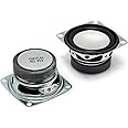
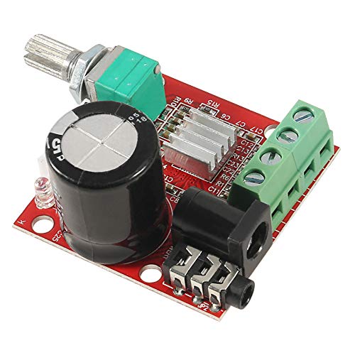
I built a small amplifier with one of these in conjunction with a reverb board. They work great with string instruments and condenser microphones.My amp was specifically for Native American flute.On the photo, you'll see the black DC coaxial power jack, the four green terminals are for two speaker (you don't have to use both if you want mono and the two white connectors are audio input. One of them is jumpered if you want mono, simply remove it for the other channel if stereo.It has built-in limiting, that will prevent burning it up if you drive it too hard. I used a 4" diameter speaker from Parts Express, they were 40w, since the speaker was loafing I had crystal clear sound.
A**.
No documentation!!!
Great little amp for the money, but I had to use my audio/electronic engineering skills to figure out how the connections are designed. It would be wonderful if it had a diagram in the description, or on a card shipped with the unit, but it doesn't.It's basically a demo board for the one chip that does everything, so you can google that chip and get a bunch of different boards that use it, along with their documentation...but they didn't match my measurements. You can also get the manufacturer's datasheet for that chip, which may be interesting, but not really useful when the circuit tracks are hidden under some big components. I thought I'd follow a screw terminal back to the chip and then see what the datasheet called that pin, but nope, can't see it. Nor can I get a probe under the heatsink without tearing it off. (let's not do that)Anyway, continuity-checking the power jack to the main capacitor gave me that polarity, so I could power it up without a 50/50 chance of destroying it. (Note: The continuity-checker says that it's connected *both* ways until the capacitor charges enough, so let it beep for a while and see if it keeps going.) I also checked the audio ground to the negative supply and saw that they were indeed connected, so that's good too. Looks like they at least followed the datasheet's recommendation for the input circuitry.Then I felt comfortable to play a sawtooth into it, created in Audacity and played on a loop, to see which of the 4 screw terminals was which. I put my old analog oscilloscope on it, and there was so much switching noise that I couldn't see anything else. So I played with an actual speaker instead. Pretty soon, I knew which two terminals corresponded to which channel, and because a sawtooth is asymmetrical, I also knew the polarity. The speaker cone jumps faster in one direction than the other, and I already know which way the signal is. A slow enough sawtooth (2Hz for me) with high enough volume allows you to just look at the cone and see it move.The standard is that a higher voltage, or higher numbers in the digital world, makes the cone push out; and a lower voltage, or lower numbers, makes the cone pull in. That's for a single driver with no crossover; a multi-way cabinet has some complex design behind it to make the emerging wavefront do that, but the drivers themselves might not. (the phase response can be nuts across the range of a multi-way speaker) So do your testing with a single driver, connected directly, even if you're eventually going to power something else with it.I've attached the results of my experimenting, so you don't have to do that yourself. It wouldn't hurt to verify though, in case they have different designs that are considered "interchangeable". Yes, they all pass audio, but the next paragraph describes a little bit of what can go wrong, even if it does "make sound".I mentioned at the top that there's some variation between this board and some others that google comes up with. The one that seemed the closest - looked identical in the picture - had the output channels swapped, and the polarity swapped on one of them. Hooking mine up that way would cause the stereo field to be backwards (something goes across the screen in one direction and across the soundscape in the other), and the centered sounds to be weird because of phase cancellations. I used that phase cancellation to check that it was indeed backwards. Playing the same thing, both speakers together were softer than either one by itself, so they were definitely out of phase with each other. But to figure out which it was, I needed the asymmetrical test tone.So if you're willing and able to do some testing and bring it up carefully, it's a great little amp for the money. But I feel like you *have* to do that, just to make it work right. You might "get sound" a bunch of other ways, but that sound may have problems as described above. So I took off a couple of stars for that.
T**S
Speaker connection Fiasco!
So many Different ideas of how to connect the speaker wires on the Ytube channel! HiLetgo pic on this site is one of many ways. However, AARON D. PICS and COMMENT I BELIEVE TO BE CORRECT! I tried pretty much all of them! At first Aaron review was confusing to me (I'm not a tech guy by any means) until I played around with it, then the review became clear! YES I would buy again, great little amp module!
B**X
Sounded Great While It Lasted
Used this amp to build an integrated audio system for my Ham radio rig. Was blown away by the sound quality for what this amp cost. But just over 30 days later, it has failed, just outside the return window.Other notes: if you aren't a bit techie, the lack of paperwork is a bit challenging.
Trustpilot
1 week ago
1 week ago