


🚀 Unleash Your Robot's Potential!
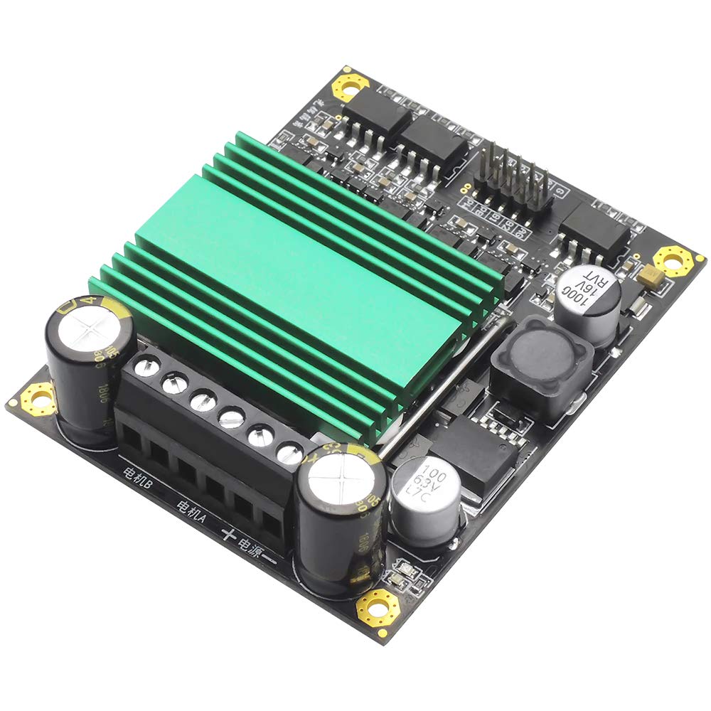
The Ultra High Power 100A DC Drive Module is a compact and efficient motor speed controller designed for robotics enthusiasts. With a high switching frequency and a robust cooling system, it ensures optimal performance for your robotic chariot in competitions and Freescale games. Its user-friendly interface and compatibility with various MCUs make it a must-have for any serious builder.
| Manufacturer | Meimotor Electronic Technology Co., Ltd. |
| Part Number | UN178 |
| Item Weight | 2.39 ounces |
| Product Dimensions | 2.76 x 0.98 x 3.15 inches |
| Is Discontinued By Manufacturer | No |
| Batteries Included? | No |
| Batteries Required? | No |
S**N
Do not run at 100% PWM duty cycle
This board worked great while it did. I was driving a 1.2HP 900W 12V DC motor, and controlling it from an ESP32 dev kit. I was quite happy with this controller during development. I set the PWM duty cycle to max out at 95%. The night before deploying this to the production environment, I decided to test it with different parameters, and set it to 100% duty cycle. As soon as I started the signal, the board burned, like in the video of one of the reviews. Another reviewer said to cap it at 99%, or the motors stop. He might have been lucky, as mine burned instead of stopping the motor.
J**M
Arduino Code to use with Motor Driver
//----------------------------------------------------------------------------// Sample Arduino code to drive 2 motors// 9-15-2019//---------------------------------------------------------------------------// Wire Pin 8 of Arduino to A1 Pin on Motor Controller// Wire Pin 9 of Arduino to A2 Pin on Motor Controller// Wire Pin 10 of Arduino to PA Pin on Motor Controller// Wire Pin 11 of Arduino to PB Pin on Motor Controller// Wire Pin 12 of Arduino to B1 Pin on Motor Controller// Wire Pin 13 of Arduino to B2 Pin on Motor Controller// Wire Gnd pin of Arduino to G pin on Motor Controller// Wire 5V Pin on Motor Controller to 5V Source// Wire Motors and Motor Voltages to Motor Controller//----------------------------------------------------------------------------// Define some global variables for Motor controlint i; // Temporary Variableint old_left_dir; // Previous Left Motor Directionint old_right_dir; // Previous Right Motor Direction#define Mot_B2 13 // Motor B B2 Output#define Mot_B1 12 // Motor B B1 Output#define Mot_PWM_B 11 // Motor B PWM Output#define Mot_PWM_A 10 // Motor A PWM Output#define Mot_A2 9 // Motor A A2 Output#define Mot_A1 8 // Motor A A1 Output// Initial Setup – This routines runs one time at start-upvoid setup() { // Turn off Motor PWM analogWrite(Mot_PWM_A, 0); // Set A PWM to “off” analogWrite(Mot_PWM_B, 0); // Set B PWM to “off” // Setup the pins to output for motor control pinMode(Mot_B2, OUTPUT); // Make B2 IO Pin an “Output” pinMode(Mot_B1, OUTPUT); // Make B1 IO Pin an “Output” pinMode(Mot_A2, OUTPUT); // Make A2 IO Pin an “Output” pinMode(Mot_A1, OUTPUT); // Make A1 IO Pin an “Output” motor(2, 0, 2, 0); // Safe all motors to “Stopped”}// Main Loopvoid loop() { // Test code for motors motor(0, 128, 1, 128); // Run left motor in reverse at half speed, right motor in forward at half speed delay(2000); // Wait 2 seconds motor(2, 0, 2, 0); // Stop both motors delay(2000); // Wait 2 seconds motor(2, 0, 0, 64); // Stop left motor, run right motor in reverse at one quarter speed delay(2000); // Wait 2 seconds motor(0, 32, 2, 0); // Run left motor in reverse at one eighth speed, stop right motor delay(2000); // Wait 2 seconds // Smoothly ramp motors up to full speed then back to stop (Forward Direction) for(i=0; i< 254; i++) { delay(40); motor(1, i, 1, i); } for(i=254; i> 0; i--) { delay(40); motor(1, i, 1, i); } motor(2, 0, 2, 0);}//-----------------------------------------------------------------------// Subroutine to move motors// dir variables: 0 = rev, 1 = fwd, 2 = stop// left / right: PWM 0 - 254 (Value checked for limits. Greater than 254 will stop motion)//-----------------------------------------------------------------------void motor(int left_dir, int left, int right_dir, int right) { // check for pwm out of limits if (left > 254) { left = 0; right = 0; } if (right > 254) { left = 0; right = 0; } if (left < 0) { left = 0; right = 0; } if (right < 0) { left = 0; right = 0; } // Process Motor Move if (old_left_dir == left_dir) { analogWrite(Mot_PWM_B, left); // No change in direction - Just adjust PWM } else { // set direction bits if (left_dir == 0) { // Reverse old_left_dir = left_dir; digitalWrite(Mot_B1, 0); // Set B1 first, just in case we were going reverse digitalWrite(Mot_B2, 1); analogWrite(Mot_PWM_B, left); } if (left_dir == 1){ // Forward old_left_dir = left_dir; digitalWrite(Mot_B2, 0); // Set B2 first, just in case we were going forward digitalWrite(Mot_B1, 1); analogWrite(Mot_PWM_B, left); } if (left_dir == 2){ // Stop old_left_dir = left_dir; digitalWrite(Mot_B1, 0); digitalWrite(Mot_B2, 0); analogWrite(Mot_PWM_B, 0); } } if (old_right_dir == right_dir) { analogWrite(Mot_PWM_A, right); // No change in direction - Just adjust PWM } else { if (right_dir == 0) { // Reverse old_right_dir = right_dir; digitalWrite(Mot_A1, 0); // Set A1 first, just in case we were going reverse digitalWrite(Mot_A2, 1); analogWrite(Mot_PWM_A, right); } if (right_dir == 1){ // Forward old_right_dir = right_dir; digitalWrite(Mot_A2, 0); // Set A2 first, just in case we were going forward digitalWrite(Mot_A1, 1); analogWrite(Mot_PWM_A, right); } if (right_dir == 2){ // Stop old_right_dir = right_dir; digitalWrite(Mot_A1, 0); digitalWrite(Mot_A2, 0); analogWrite(Mot_PWM_A, 0); } }}
S**N
Works well but died
I didn’t get the black version PCB version. I don’t mind much, but it would be nice to have the same colors as the image.The unit does not come with the 10-12v fan connector you see in the image. I have to use an external fan to cool this unit down.It ran very good then all of the sudden it just dies within a month. No smoke no nothing.Cost too much. Prob shop somewhere else.
O**R
It really does 100 amps!
Many of these motor controllers are pretty optimistic in their ratings, but this UN178 board really can switch 100 amps per motor.This weekend I did some stall tests driven from an Arduino on our mining robot. Our stall tests showed one motor control channel on this board fed from 24 volts DC stalled at 105 amps feeding one locked-rotor DC motor. I had a mechanical failure (tore two inch-wide polypropylene straps in half!) at 62 amps when trying to stall two DC motors while using both output channels, but this motor controller was still working fine. I supplied the board with 24 VDC power from two 5000 mAh 20C 3S lipo batteries in series (at these currents, you need pretty serious batteries.) This same test has fried solid state relays labeled "40A" and hit the current limit on several weaker motor driver boards, so I'm really happy with this board!The documentation above is not quite English, but the board's six big pins with screw terminals are labelled as: + -: Input battery power, 12-48VDC 电机A: Output terminals for motor A 电机B: Output terminals for motor BThe big screw terminals easily fit solid core 12 gauge wire, and solid core 10 gauge is likely doable, although stranded 10 gauge wire would be a tight fit. At 12VDC, the board pulls 58mA static current, even with all motors stopped, probably to power the onboard opto isolators.The board's ten small logic input pins have male headers at the usual 0.1 inch pin spacing with these labels: G: input pin for logic ground. Tie this to Arduino ground. A1, A2: input digital direction pins for A motor. 1,0 or 0,1 turn the motor in different directions. If you leave the pin disconnected, it acts like it is pulled low. B1, B2: same direction pins, but for B motor. PA: input PWM pin for A motor. Set to 0 for off, or send in a PWM duty cycle to set the motor power. You cannot set this PWM pin to a fixed static 1 value (100% duty cycle) or else the board will rapidly stop powering the motors, so cap your duty cycle to 99% on time, so the board sees some changes on the PWM input pin. PB: same PWM pin, for B motor.These logic input pins don't need to be connected: AG: connected to battery - terminal, isolated from logic ground. I think this is only provided so you could measure the millivolts on this wire to use the board itself like a shunt resistor to estimate the motor current. It's safest to leave this line disconnected, and the board works fine with the input disconnected. (If you tie logic ground to battery ground, and the battery ground terminal comes loose, the motor current will backfeed through the logic side and fry your microcontroller.) 5V: seems to be a decoy terminal: no input pulled or required; no output provided. PW: does not appear to be connected on the PCB.Now that I've figured out how it works, I plan to buy more of these boards.
Trustpilot
4 days ago
2 weeks ago


