

💡 Light Up Your Innovations!
The GeeekPi2Pack MAX7219 8 x 32 Dot Matrix MCU is a versatile LED display module designed for seamless integration with Arduino and Raspberry Pi. With a resolution of 32x8 LEDs, it comes complete with essential accessories for easy setup and expansion, making it ideal for both hobbyists and professionals looking to enhance their projects.
C**E
One of the best deals you can get.
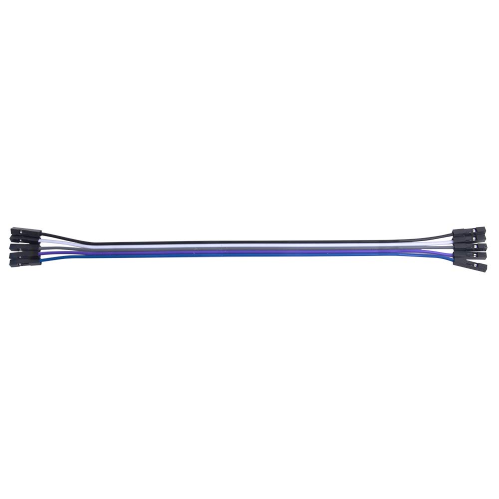
The media could not be loaded. To start off: Great packing, Almost no waste, came with great quality dupoint wires, and 2 Velcro cable ties. (For your sake please solder max7219’s to your preferred control board they are much more reliable this way) they barely get warm under a normal brightness mode. And was easy to setup the code (dont use the md_max2xxx or md_ libs they dont seem to like any max7219 device) they are very responsive and have a extremely low passthrough resistance for daisy chaining many modules. As a note, they have a diffused look. The actual matrix is hot-swappable. Overall they completed my project on a great note. Highly Recommended for any makers
T**T
Large letters possible
Large letters possible!
T**L
Ideal for Hell Schreiber decoder
The media could not be loaded. These LED matrix displays are very easy to interface with and use. There are several Arduino libraries to choose from to display English alphabet characters and Arabic numbers, plus any user defined sprites. For my application (displaying received Hell Schreiber characters with 7x7 dot matrix), I adopted and made additional changes to code from a library called MaxMatrix. Keep in mind that these modules are meant for Chinese , whose traditional books (written on bamboo sticks) are organized to read characters from top to bottom. So the module is positioned such that characters go top to bottom, unlike the western mode of left to right. Thus, in the left-to-right arrangement, the “columns” and “rows” are actually “rows” and “columns”.
J**A
Muy bueno
The media could not be loaded. Excelente producto buena calidad y diseño fácil de montar
R**T
Female Headers not soldered properly
Took only a few seconds to figure out why each segment wasn't flush with the other. The female pin headers on the board were not fully inserted, so some were higher than the others. Pretty disappointed in the poor quality. Would have given it one star, but gave it an extra since only one of two units were this way. some variation in the second one, but barely noticeable in comparison to the first.Would return, but I'm going to try to fix just to see if I can.
R**N
Reversed Arduino Text
These modules work great and are a very fair price. BUT, if you are using them with Arduino and the popular MD_PAROLA library, you need to know that the hardware setting must be adjusted. In the example sketches for the Parola library, you will find the line #define HARDWARE_TYPE MD_MAX72XX::PAROLA_HW Replace "PAROLA_HW" with "FC16_HW" to get this display to work properly. I had to dig on Google for an hour to find this out, otherwise five stars.
S**O
Fragile with dumb pins
These come preassebled with the connector pins straight off to the side. That’s a problem if you’re intending to put it in a case. They include a 90 degree right angle pin set, but no matter if I try to desolder with an iron or with a hot air tool, I manage to hose this connection point every time. There’s something amazingly fragile in this design.
W**L
Works but there are different hardware variants!
These were easy to get to work with Arduino Nano, Uno and a ESP8266 NodeMCU microcontrollers. I have not yet tried them with a Raspberry Pi.One gotcha I found is that there appear to be at least 2 variations of this product. The first version has gaps between the 8x8 LED matrices and the PCB with the MAX7219 chips on it taking an extra 1.5-2 rows on a solderless breadboard. The markings indicating IN-> OUT -> are on the top of the mounting PCB, making it slightly more difficult to determine which end to place the wires. The other has no gaps between the 8x8 LED matrices and has the IN -> OUT -> markings on the bottom of the PCB. I don't know which one would be considered the current version.Another possible caveat is that the header pins are at a 90 degree angle. If you wanted to connect two of these modules end-to-end (like I did), then the header pins must be desoldered and straight header pins soldered in to replace them. Another benefit of straight header pins is that the product can be mounted on a solderless breadboard (but will span three breadboards).While I would like to order more of these, the chance of a **third** hardware variant makes me a little wary of doing so.
Trustpilot
2 months ago
1 day ago